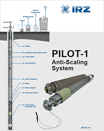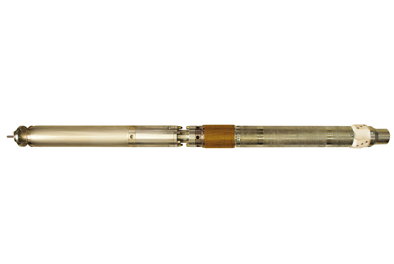
PILOT-1 is a patented system designed to reduce scaling on outer and inner surfaces of downhole equipment and to achieve highest efficiency of well operation.

| No. | Parameter | Value |
|---|---|---|
| 1 | Characteristics of reservoir fluid | |
| 1.1 | Reservoir fluid | Liquid gas mixture consisting of oil, formation water, well gas and solids |
| 1.2 | Liquid density, kg/m3 | 700—1400 |
| 1.3 | Formation water PH | PH 4.0—8.5 |
| 1.4 | Max water ratio in produced fluid, % | 100 |
| 1.5 | Maximum hydrostatic pressure at downhole unit location | Up to 30 MPa |
| 1.6 | Maximum cable length | 3000 m |
| 1.7 | Maximum temperature of reservoir fluid, degrees C | 120 |
| 2 | System components | |
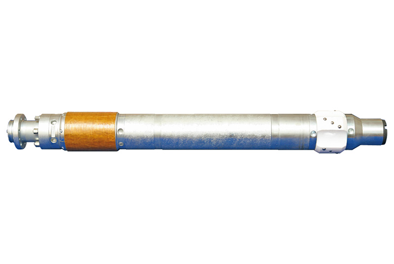
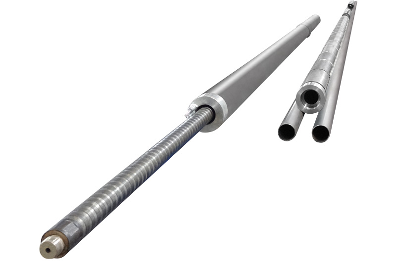
| — Downhole electromagnetic unit — Downhole monitoring system with optional motor cross-over |
||
| 3 | Functional characteristics | |
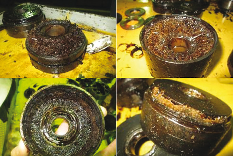
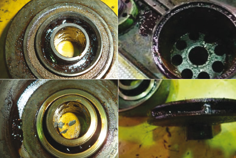
| 3.1 | Prevention of scale formation on the outer and inner surfaces of downhole equipment (ESP, tubing, etc.) by action of electromagnetic field inhibiting salt crystals formation in the produced fluid along the entire wellbore — from bottomhole to wellhead | |
| 3.2 | Measured parameters | The list of monitored parameters and specifications depends on the downhole monitoring system in use. Parameters of DH EM unit monitored by the system: 1) Radiator current (A): 0…0,5 A 2) Radiator supply voltage (V): 0…100 V Parameters monitoring error: +/- 2% Monitoring resolution: 0,01 Every parameter is measured and transmitted via downhole monitoring system while the motor is in operation. The surface read-out unit of the DH monitoring system transmits data from the downhole sensor to the controller of the motor drive using MODBUS protocol. Measured parameters can also be transmitted by GSM modem (optionally). |
| 3.3 | Data link | Digital |
| 3.3.1 | Data link between surface and downhole units | PILOT-1 is connected to motor through the downhole sensor of the DH monitoring system. Data is being transmitted through the zero point of the motor’s stator — power cable — high-voltage winding of the transformer |
| 3.4 | Operating voltage of Motor | From 1000 V to 4000 V |
| 3.5 | Power supply of the downhole electromagnetic unit | Supply voltage of the downhole unit is 16 to 70 V. The downhole unit is powered by additional stator winding of the motor (30 to 100 Hz AC power sine wave filter). Modification of motor required to secure connection |
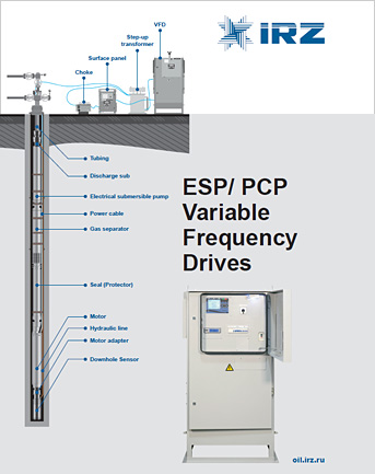
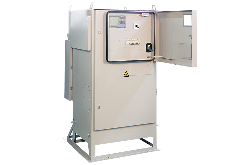
| 3.6 | Surface Readout Unit | Surface Readout Unit is to be installed in VFD. Supply voltage of the unit is 220 V ±15% Optionally, a stand-alone panel can be supplied (equipped with display and data storage logging possibilities) |
| 3.7 | Current consumption of downhole unit | Max. AC: 2 A |
| 3.8 | Frequency of electromagnetic radiation | Frequency of electromagnetic radiation of the downhole unit is between 50…250 kHz |
| 3.9 | Motor cross-over (adapter) | Designed based on motor drawing |
| 3.10 | Resistance to interference | The system ensures reliable data communication from the well, regardless of the operating conditions and the completeness of surface electrical equipment. It withstands voltage interferences with higher harmonic components, as well as insulation resistance drop on cable and motor (up to 30 kOhm) |
| 3.11 | Overall dimensions of downhole electromagnetic unit | The maximum diameter of the housing is 124 mm |
| 3.12 | Housing design | DH EM unit housing with internal thread, 60 mm pipe tubing (GOST 633) is capable of carrying accessories up to 500 kg |
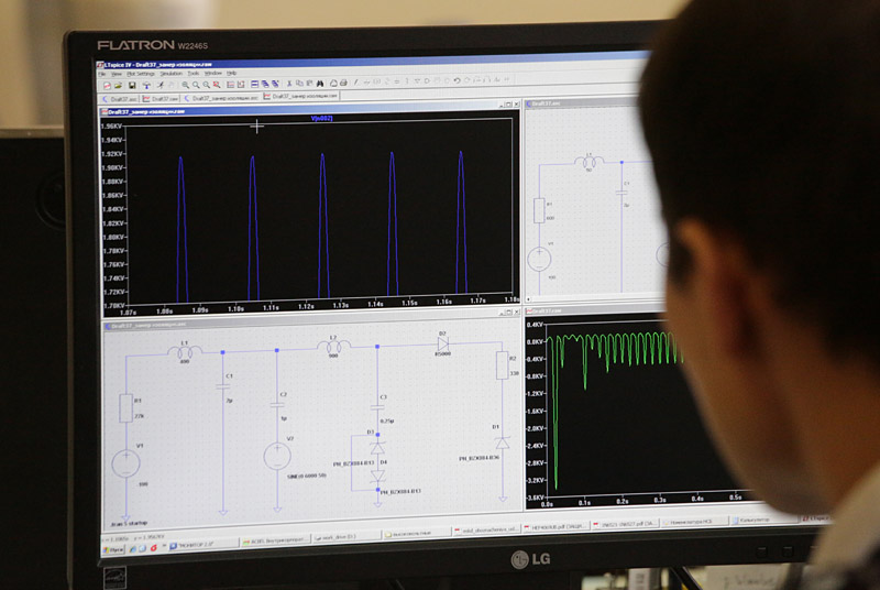
| 3.18 | Functional tests | Equipment is tested on Simulator to determine which part of the system (surface or downhole) fails, with still live control station. The Simulator Unit is supplied for every 5 Pilots. If only one Pilot is in delivery scope, then 1 Simulator will be supplied nevertheless |
| 3.19 | Repairability | During the warranty period the system shall be repaired by supplier |
| 3.20 | Coating of housing and other outer elements | The outer surfaces are coated with paint which is resistant to mechanical stress and corrosive environments |
| 4 | Reliability and effectiveness of equipment | |
| 4.1 | In case of failure of the system | PILOT-1 failure does not lead to the failure of ESP unit |
| 4.2 | Warranty period | 24 months from the date of shipment, 12 months from the date of putting into operation |
| 4.3 | Scale prevention efficiency | During its lifetime (2 years), the system prevents scale formation on inner and outer surfaces of submersible equipment (ESP, tubing etc.) |
| 4.4 | Lifetime | 2 years |
| 5 | Operational safety | |
| 5.1 | Design | The design conforms to the safety requirements of oil and gas industry in Russia |
| 6 | Delivery set and engineering support | |
| 6.1 | Documentation and delivery set | — Pilot-1 — Operational documents — Simulation Unit — Spare parts and accessories |
| 6.2 | Engineering support | Training of customer personnel, setting the system at service base, connection to Motor, periodic monitoring of operation mode, maintenance during warranty period |
AC electromagnetic field action modifies fluid structure, and results in formation of fine crystals lifted on the surface, preventing downhole equipment scaling.